TOP SECRET
robot update notes

Welcome again to bent machine labs.

"bent machine labs: Desire is our one true engine." (TM.)

TOP SECRET
June 2000 update


Leg designs:

Most of the time I had for robot projects this month was spent working on my homebrew servo controller. In anticipation of being able to add another degree of freedom (DOF) to each leg, though, I have been tossing around a few new leg designs.

The robot currently tends to shimmy from side to side as it walks forward. This is obvious in one of the eight-second exposures I posted last month. Check out the paths traced by the LEDs. I would like to at least decrease this shimmy a bit. Also, it would be interesting for the robot to be able to walk sideways, and finally, the robot would benefit from an increase in stride length when walking forwards.

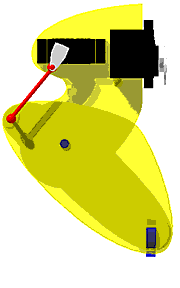
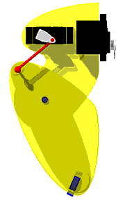
Here's something I put together with these goals in mind. This design was created with an eye towards disturbing the current aesthetic of the robot as little as possible. A few preliminary sketches have been done with an eye towards a complete rebuild of the robot as well.


Servo controller design update:

The servo controller is just about completely programmed. All that really remains to do is insert some balancing pauses. Also, some of the code could use cleanup and optimization. It is, however, currently functioning up to spec in my testing.

This coming month I should be able to build a controller board with two controller chips so I can have 3 DOF on all four legs of Petal. Although I plan to do so eventually, I feel it would be irresponsible to release the software and circuit diagrams until I subject my software and hardware to real world application and testing in my robot.

Unanswered questions which have to wait for real world testing:
1) My testing seems to indicate that movement will be pretty smooth, but it may turn out that there is some vibration depending on the load the servo is moving and the particular speed setting.
2) It stands to reason that due to the way speed control is implemented, overall torque may be somewhat compromised.
3) With any software, there are always bugs which don't emerge until you actually begin to use it.


Speed Control Theory of Operation.

Hobby servos actually have some acceleration and deceleration built into their hardware. They also move somewhat more slowly when they are traveling shorter distances. My software is designed to take advantage of these two factors. Instead of taking the target position from the user and feeding that straight to the servo, the control software breaks the requested movement into increments, so that the servo is always either accelerating or decelerating. As could be expected, more increments lead to slower movement.

The goal is to update fast enough that the servo is always playing catch-up to the controller's requests. I doubt it is by coincidence that updating all servos at 50 MHz does the trick.


Servo control (for the curious)

This is a simple explanation of how my servo controller chip currently works.

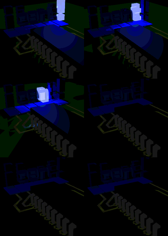
Imagine you're writing a program which lights a series of lamps, one at a time. (Ok - maybe I had a little too much fun with the animation. Don't mind me, just "promoting my corporate image.") First it lights lamp one, then lamp two, then lamp three. You get the idea. After it does the sixth lamp, it goes back to lamp one.

The process of turning a lamp on and off we'll call a pulse.

The progression from lamp 1 to lamp 6 we'll call a cycle.


Now imagine speeding this up fast enough that you are doing 50 cycles a second (50 Hz.) At this speed, each cycle would take 20 milliseconds (1 millisecond = 0.001 seconds = 1 ms.) At this point, the lamps are being pulsed so fast that it looks like they're on all the time.

Now what you need to do is vary the time each lamp is on. The length of each pulse will be from 1 to 2.5 milliseconds. (The term for varying pulse lengths like this is "pulse width modulation" or PWM.) To keep every cycle the same length, pauses need to be inserted after each lamp pulse. So, a 1.5ms pause needs to be inserted after a 1ms pulse, a 0.25ms pause would follow a 2.25ms pulse, etc. This way, each lamp is serviced for 2.5ms.

Easy enough, but if you add up six 2.5ms time periods, a complete cycle only uses up 15ms, so there is time left to do some other things. With a PIC clocking a 4MHz, 5 milliseconds is long enough to do A LOT of stuff. Here's why: Most instructions are done in 1 microsecond (One microsecond = 0.000001 seconds = 1us.) To create a 1 millisecond pause, the PIC has to count to 1000. Five milliseconds is enough time for (best case) 5000 instructions.

This gives the PIC enough time to receive servo positioning information, do some housekeeping, collect various information, reply back to us, AND the PIC has to burn a ton of time on top of that.

Once this is all set up, one just takes away the lamps, and puts servos where the lamps were. Each servo looks at the pulses it receives, and adjusts its position to reflect how long each pulse is.

The relationship between pulse width and servo position has been given so much attention on the web that I will decline to get into it here. A treatment of this subject is available on the Portland Area Robotics Society site. (Note that this article also contains instructions for hacking a servo for continuous motion, which is not relevant to this discussion.)


Very informal current specifications (for the technophile)

The servo controller chip was designed to be a relatively cheap modular solution for controlling hobby servos. Each chip can control up to 6 servos, and has three inputs for various switches. The servo control includes 4 bit variable speed control. When the speed control feature is activated, the software performs acceleration and deceleration as well.

The range of motion for all servos is approximately 115 degrees. The resolution of this range is 8 bit.

Until I find a better solution, each chip requires at least two wires for communication. These two wires are used for serial in to the controller. A third, optional serial out wire is needed to receive the status transmission from the controller. This transmission includes the status of the three switch inputs, a flag which indicates whether or not all servos have reached their destinations, and helpful debugging information. All serial communication is currently conducted at 19600 baud, no parity, non-inverted.

The controller will check for incoming serial once per cycle. If reception begins, it will wait for two bytes. The first byte should contain the speed control setting (in the low nibble) and the number of the servo to control (a.k.a. servo select, located in the high nibble.) If the servo select value is out of range, the controller disregards both bytes it received in that transmission. The controller signals that it has received a valid transmission with a green LED.

The servo controller PIC can control up to 6 servos at a time. I chose 6 because with two controllers on a board you've got 12 servo outputs, which is enough to drive a hexapod with two DOF per leg, or a quadruped with three DOF per leg. With 3 on a board you've got 18 servo outputs, which is enough to drive a hexapod with three DOF per leg, or an eight-legged robot with two DOF per leg. Six just turned out to be nice and even.

: YAWN :

Three pins of the servo controller may be used for digital input. These would be ideal for bumper switches on the legs or tactile switches on the feet, or whatever, as long as the input is digital (on or off.) The information from these pins is sent back in the serial transmission.

The four bit speed control has a large range of speeds. Speeds 1 through 3 are designed to be slow, with speed 1 only updating servo position every 40 cycles. Speeds 4 through 14 are progressively faster, and include built-in acceleration and deceleration.

Speed 15 turns off speed control, so the servos will work as they are designed to.

Speed 0 effects an immediate halt. The commanded servo or servos will stop moving exactly where they are, and hold position until a different speed setting is selected. Of course, there is no way to tell where the servos stopped, but I'm sure this feature will have its uses. This feature won't really work when speed control is off (speed = 15.)

At very slow speeds (speed settings 1 and 2) I have implemented software resolution enhancement which makes the movement a bit smoother. This enhancement takes advantage of the fact that servo position is not updated every control cycle, and effectively adds another three bits to the servo resolution.

According to my low tech testing, speed control has little effect on the average current drawn by the servos. Any difference only becomes appreciable when using speed settings 1 through 3, where my measurements indicate current draw drops by at least 50%.


You can wake up now, it's over. That's about it for this month's update. More to come next time.


back

home


Everything copyright, 2000 Dave Benz

hits counter